Posts

Showing posts from February, 2018

Cabin Door

Cabin door is installed on each side of the airplane. Each door has an outer sheet skin that is chemically bonded to an inner pan assembly. Each door has a latch assembly, an inside handle, a pair of external hinges, and a doorstop assembly.                  Cabin Door Adjustment/Test A. Adjust the new cabin doors. CAUTION: Do not adjust the bonded door flange or the airplane structure with force. Damage to the bonded areas and the structural components can occur. (1) Trim the door flange as required to get a gap between the door skin and fuselage skin of 0.09  inch (2.3 mm) or less. B. Adjust the cabin doors. NOTE: The cabin doors must be smooth with the fuselage skin. (1) Use the slots at the door latch plate to adjust the latch assembly and the bolt engagement  with the rotary clutch on the door post.
Fuselage

Image
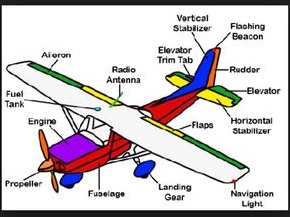
TTP B1-L3 ATA53 Cessna 172 B2-L1 Fuselage  - semimonocoque construction and consists of three major sections: forward section , center section , and tailcone section . Construction consists of formed bulkheads, longitudinal stringers, reinforcing channels and skin. Frame members of the cabin section are constructed of formed bulkhead channels. Bulkheads are formed "U" channel sections. Principal material is 2024- 0 alclad aluminum alloy  which, after forming, is heat treated to a 2024-T42 condition and painted with epoxy primer. All bulkheads in the fuselage are constructed of formed sheet metal or reinforced sheet metal. Wings are of all-metal, strut-braced, semi monocoque construction, utilizing two spars. Each wing consists of an outer wing panel with an integral fuel bay, an aileron and a flap. Flanged upper and lower edges of all ribs serve as cap- strips, in addition to providing rigidity to the rib. The skin, riveted ...

FAA AD 2018-02-04

 Aerospace Welding Minneapolis, Inc. applicable on Muffle installed on Cessna 172R/S.   Effective Date of this AD is  February 21, 2018 Muffler part No. A1754001-23   172R S/Ns 80001 and up; 172S S/Ns 8001 and up. Muffler part No. A1754001-25   172R S/Ns 80001 and up; 172S S/Ns 8001 and up;        This AD was prompted by occurrences of cracks or broken welds in the connecting weld of the muffler body to muffler cuff that may allow carbon monoxide (CO) exhaust fumes into the cockpit heating system. We are issuing this AD to prevent cracks in the connecting weld of the muffler body to muffler cuff that may allow CO fumes to enter the cockpit heating system and possibly inhibit the pilot's ability to maintain control of the airplane. Compliance : Comply with this AD within the compliance times specified, unless already done. Inspection of the Muffler        (1) Within 5 hours time-in-service after Febru...

Light

          TTP Cessna 172 B1 L3 ATA33 Light B2 L3    Single white neon tube  under glareshield provides overall lighting for the instrument panel. Glareshield dimming control is mounted below and to the left of the throttle. The flight instruments individually light by a replaceable light bar assembly. The light bar assembly is at the top of the instrument. Engine instruments are individually lighted by replaceable light bulb assemblies. Both flight and engine instruments are operated by a dimming control unit. Radio lighting consists of internally lighted radios, a dimming module and a dimmer control. Map light is installed on the lower surface of the pilot’s control wheel. Navigation lights - The airplane is equipped with both fixed intensity navigation lights and pulsing strobe lights. Navigation lights are located on the left wing tip, right wing tip and tailcone. The navigation lights in the wing tip a...

Fuel System

TTP Cessna 172 Cat.B1 Level -3 ATA28 Fuel System Cat.B2 Level -2 Cessna 172 R has a wet wing fuel storage system with two integral fuel tanks (one in each wing), a three position selector valve , a fuel reservoir tank, an electrically-driven auxiliary fuel pump, a fuel shutoff valve and a fuel strainer. Components forward of the fuel strainer include the engine-driven fuel pump, the fuel injection servo and the fuel distribution valve. Fuel bays may need to be resealed if a leak has developed, or if the wing has been repaired. These procedures provide instructions for sealing fuel bays, classifying fuel leaks, and testing fuel bays after repair. PTP Cessna 172 B1 LOC FOT SGH R/I MEL TS B2 LOC FOT SGH MEL   282003 Fuel Selector Valve - Check controls for  detent in each position, security of attachment, and for proper placarding. B 05-12-01 224 282005 F...

Electrical power

                  TTP B1-L3 ATA24 Cessna 172 B2-L3 Electrical energy   is supplied by a 28-volt, direct current, single primary bus, negative ground electrical system. A single 24-volt main battery supplies power to the starting system and gives a reserve source of power if an alternator failure were to occur.  Garmin G1000 system have a second battery known as the Standby Battery. Standby Battery is controlled and monitored by the Standby Battery Controller and supplies power to the G1000 Essential Bus if there is a failure of the main battery and alternator. Power junction box, (MCU), is attached to the forward left side of the firewall and includes electrical relays, an alternator control unit (ACU), an ammeter sensor, an external power receptacle, fuses and/or circuit breakers in a single box. Engine-driven alternator is the normal source of power during flight and maintains...

Flight Control System Operation Electrical

TTP B1----- ATA27A Cessna 172 B2-L3                           Flap- control system has an electric motor and transmission assembly, drive pulleys, push-pull rods, cables, and a follow-up control. Power from the motor and the transmission assembly goes to the flaps by a system of drive pulleys, cables, and push-pull rods.  Electrical powe r to the motor is controlled by two MSW mounted on a floating arm assembly, a cam lever, and a follow-up control. As the flap control lever moves to the necessary flap setting, the attached cam activates one of  the microswitches, and that activates the flap motor. As the flaps move to the necessary position, the floating arm is turned by the follow-up control until the active microswitch clears the cam. The circuit breaks and the motor stops.   To move the flap in the opposite direction , the control lever is moved in the opposite direction....